Anti-Surge Leadless 0204 0207 0309 SMD Fusible Wire Wound MELF Carbon Metal Film Resistors 0.125W 0.25W 0.5W 1W 2W
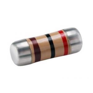
Metal Electrode Leadless Face (MELF) Resistors are round or cylindrical in shape. They are available in embossed plastic tape on 7" reels. The terminals on MELF resistors are force-fitted steel caps with Sn plated termination. Parts are also available in Zero-Ohm value. Land pattern sizes for MELF resistors are the same as SMD chip resistor.
Notes
* MELF is the acronym for Metal Electrode Leadless Face.
* 90/10 solder plated end caps.
* Suitable for reflow and wave soldering.
* Meets or exceeds EIAJ 8009, EIA PDP 100.
* Force fitted steel caps are tin plated. SnPb is available upon request based on availability.
* Tape type is plastic.
Application filed
This standard applies to electric light sources, switching power supplies, chargers, communication equipment, medical electronic equipment, test and measurement equipment, automobiles.
Replacing plug-in resistors in electronic equipment such as electronics, industrial products, and household appliances.
Features
1) Use non-combustible / epoxy resin coatings with safety features of non-combustible and insulating;
2) Miniaturization for high-density placement;
3) Meet the requirements of lead-free (Pb) and lead-containing soldering processes;
4) Can be used in automatic surface mount (SMD) assembly systems. Suitable for automatic welding by wave soldering and reflow soldering;
5)SMD enabled structure
6)Flameproof multi-layer coating equivalent to UL 94 V-0
7)Flameproof feature equivalent to overload test UL 1412
8) Enhanced weld spot is reliable against surge
9)Products meet RoHS requirements and do not contain substances of very high concern identified by European Chemicals Agency
10) Specifications Per IEC 60115-1, 60115-4
Dimensional Drawing
| Size | Dimension(mm) |
| L | D1 | D2 Max. |
| 0204 | 3.5±0.2 | 1.1±0.1 | 1.4±0.2 |
| 0207 | 5.9±0.2 | 1.7±0.1 | 2.1±0.2 |
| 0309 | Single cap 8.5±0.2 Double cap 8.7±0.2 | 2.5±0.1 | Single cap 3.1±0.2 Double cap 3.0±0.2 |
Material info
| Code | Name | Material |
| 1 | Coating | Non-combustible / epoxy resin coating |
| 2 | Color ring | Flame retardant coating |
| 3 | Cuting wire | -- |
| 4 | Fuse element | Alloy wire |
| 5 | Magnetic bar | Alumina ceramic body / resistive film |
| 6 | Cap | Tinned iron cap |
Part numbering
KNPM : Series name
1 : Power Rating -- 0.125W,0.25W,0.5W,1W,2W.
100 : Resistance value -- E24 norminal resistance
J : Resistance tolerance -- F=±1%,G=±2%,J=±5%
S : Size code -- It is normal size without code; S- small size ; X-Ultra-small size.
Electrical specifications
| Size Type | Power range(70C) | Temperature range ℃ | Insulation voltage V | Resistance range(Ω) |
| ±1%,±2%,±5% |
| 0204 | 0.125W 0.25WS 0.5W-X | -55 ~ 155 | 200 | MFM 0.1~2.2M CFM 1~10M MOFM 1~10K |
| 0207 | 0.25W 0.5W-S 1W-X | -55 ~ 155 | 250 | KNPM 0.22~100 MFM 0.1~10M CFM 1~10M MOFM 1~10K |
| 0309 | 0. 5W 1W-S 2W-X | -55 ~ 155 | 350 | KNPM 0.22~300 MFM 0.1~10M CFM 1~10M MOFM 1~10K |
General datas
| Nominal resistance tolerance | ± 5% |
| Climate category | 55/155/21 |
| Low air pressure | 8.5kpa |
| Stability level | 5% |
| Resistance change | Limit value |
| Long-term test | ±(5%R+0.1Ω) |
| Short-term test | ± (1% R + 0.05 Ω) |
| Rated current | I2(A)=P(W)/R(Ω) |
Tape size
| Size | φA (mm) | φB (mm) | φC (mm) | W | T | QTY(pcs) |
| 0204 | 179±2 | 60±2 | 13±0.5 | 9±1 | 12±0.5 | 3000 |
| 0207 | 179/330±2 | 90±2 | 13±0.5 | 10±1 | 14.5±1 | 2000/5000 |
| 0309 | 330±2 | 90±2 | 13±0.5 | 16±1 | 19.5±1 | 2500 |
Paper Size
| Size | Dimension(mm) |
| A | B | W | E | F |
| 0204 | 1.6±0.2 | 3.8±0.2 | 8.0±0.2 | 1.75±0.1 | 5.25±0.1 |
| 0207 | 2.4±0.2 | 6.0±0.2 | 12.0±0.2 | 1.75±0.1 | 7.25±0.1 |
| 0309 | 3.6±0.2 | 8.9±0.2 | 16.0±0.2 | 1.75±0.1 | 9.25±0.1 |
| | P0 | P1 | P2 | D0 | T |
| 0204 | 4.0±0.1 | 4.0±0.1 | 2.0±0.1 | 1.5±0.1 | 1.65±0.1 |
| 0207 | 4.0±0.1 | 4.0±0.1 | 2.0±0.1 | 1.5±0.1 | 2.5±0.1 |
| 0309 | 4.0±0.1 | 8.0±0.1 | 2.0±0.1 | 1.5±0.1 | 3.5±0.1 |
Color marking
| Color | First digit | Second digit | Third digit | Malutiplier | Tolerance |
| Black | 0 | 0 | 0 | 100 | - |
| Brown | 1 | 1 | 1 | 101 | ±1 |
| Red | 2 | 2 | 2 | 102 | ±2 |
| Orange | 3 | 3 | 3 | 103 | - |
| Yellow | 4 | 4 | 4 | 104 | - |
| Green | 5 | 5 | 5 | 105 | ±0.5 |
| Blue | 6 | 6 | 6 | 106 | ±0.25 |
| Violet | 7 | 7 | 7 | 107 | ±0.1 |
| Gray | 8 | 8 | 8 | 108 | - |
| White | 9 | 9 | 9 | 109 | - |
| Gold | - | - | - | 10-1 | ±5 |
| Sliver | - | - | - | 10-2 | ±10 |
| Plain | - | - | - | - | - |
Reliability Test
| Characteristics | Test Conditions | Limits |
| Short Time Over Load | IEC 60115-1 4.13 5 seconds 2.5x rated voltage (not over max. overload voltage) | ±2% |
| Load Life In Humidity | IEC 60115-1 4.24 56 days rated load (not over max. working voltage) at (40±2)°C and (93±3)% relative humidity | |
| Load Life 1,000 hours | IEC 60115-1 4.25.1 Rated load (not over max. working voltage) with 1.5 hours ON, 0.5 hours OFF, at (70±2)°C | ±5% |
| Resistance To Soldering Heat | IEC 60115-1 4.18.2 Dip the resistor into a solder bath measured (260±5)°C and hold it for a 10±1 seconds | ±1% |
| Solderability | IEC 60115-1 4.17.2 Solder area covered after (230±3)°C/(2±0.2) seconds with flux applied | 95% Min. |
| Vibration | IEC 60115 4.22 Six hours in each parallel and axial direction with a simple harmonic motion having an amplitude of 0.75mm and 10 to 500 Hz. | ±1% |
| Thermal Endurance | IEC 60115-1 4.25.3 1000 hours at 200°C without load | ±1% |
| Thermal Shock | IEC 60115-1 4.19 -55°C 30minutes, +155°C 30minutes, 5 cycles | ±3% |
| Surge Test | Surge voltage = 12,000PR DC P is power rating, R is resistance value, surge voltage is not more than listed at right. Surge spec = 1.2/50µs Period = 60 sec Number of surges = 100 | ±5% |